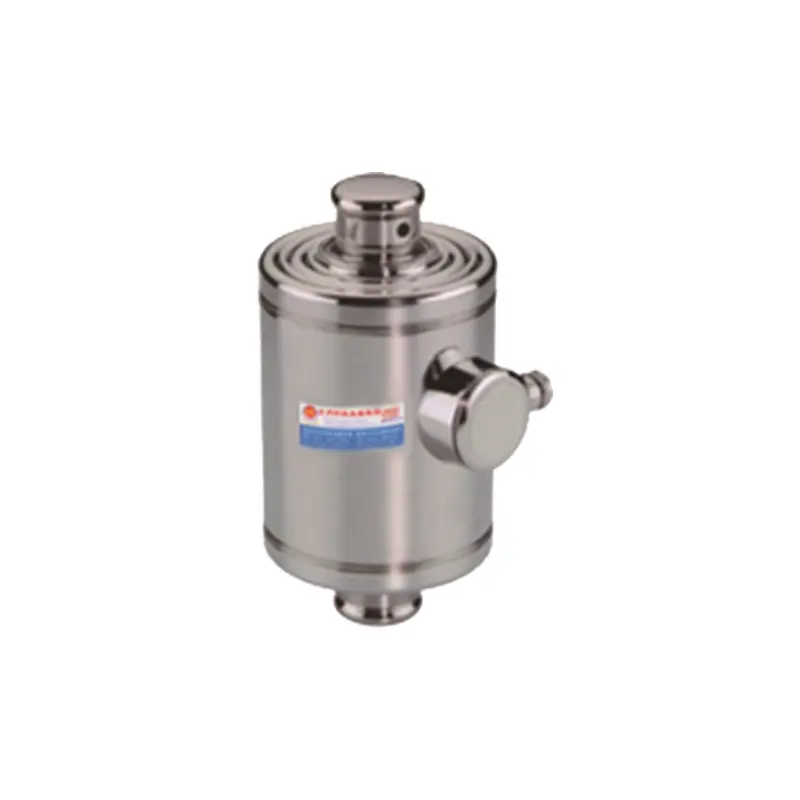
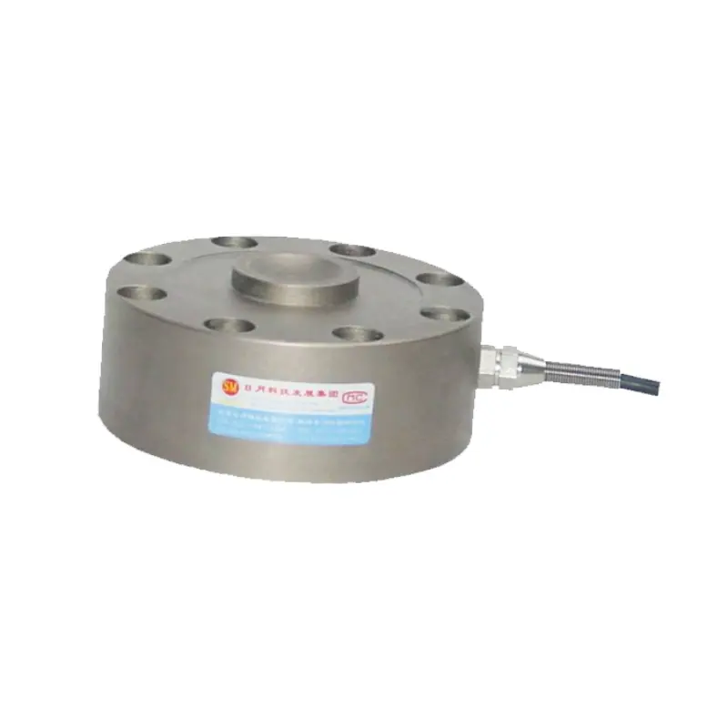
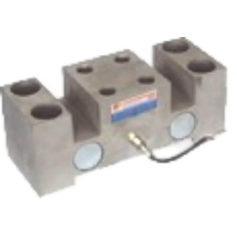
The QCX series bearing block load cell is mainly installed under the bearing housing and can also be used in other structural forms. It is a dedicated sensor mainly for measuring the bearing capacity of a certain type of bearing housing.
The structural principle is a shear-type resistance strain sensor with both ends fixedly supported and the center bearing. Selected high-quality alloy steel as the elastic body and foil-type resistance strain gauges as the sensitive conversion elements.
The socket is installed in the middle of the sensor, and the two ends of the sensor are fixed on the base. When the bearing housing is in load, the load is transmitted to the base through the shear elastic beams at both ends, generating strain proportional to the load in the elastic beams, which is converted into corresponding electrical signals by strain gauges.
Perceive the world Connect the world Innovate the SUNMOON
Description
The QCX series bearing block load cell is mainly installed under the bearing housing and can also be used in other structural forms. It is a dedicated sensor mainly for measuring the bearing capacity of a certain type of bearing housing.
The structural principle is a shear-type resistance strain sensor with both ends fixedly supported and the center bearing. Selected high-quality alloy steel as the elastic body and foil-type resistance strain gauges as the sensitive conversion elements.
The socket is installed in the middle of the sensor, and the two ends of the sensor are fixed on the base. When the bearing housing is in load, the load is transmitted to the base through the shear elastic beams at both ends, generating strain proportional to the load in the elastic beams, which is converted into corresponding electrical signals by strain gauges..
Characteristics
1. Strong anti-interference ability, is convenient to install and use, and has good stability.
2. The flat plate shape ensures a stable force state, good lateral interference, and can achieve high measurement accuracy.
3. Strong overload capacity and used for overload alarm of bridge cranes.
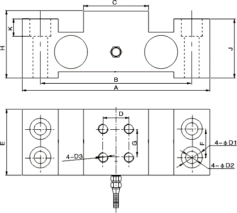
Dimensions(In mm. 1mm=0.03937 inches)
CAP./SIZE
A
B
C
D
L
L1
L2
ø1
t/mm
1.5
350
310
38
75
152
100
40
17
2.5
410
355
50
100
182
130
60
21
4
410
355
50
100
212
160
60
21
10
410
355
50
100
212
160
60
21
Ib/inches(conversion of above dimensions)
3306.93
137.80
122.05
14.96
29.53
59.84
39.37
15.75
6.69
5511.56
161.42
139.76
19.69
39.37
71.65
51.18
23.62
8.27
8818.49
161.42
139.76
19.69
39.37
83.46
62.99
23.62
8.27
22046.23
161.42
139.76
19.69
39.37
83.46
62.99
23.62
8.27
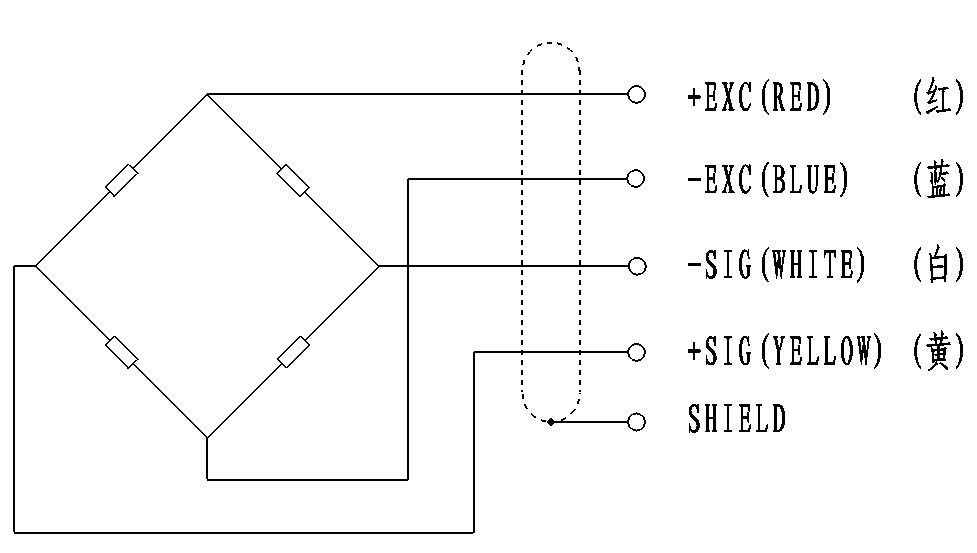
Circuit Diagram:
Red: +input
Blue: -input
White: +output
Yellow: -output
Specification:
Type
Technical parameters
Nominal load range
10~50t
Power supply
10~12 VDC
Zero balance
1.0±% of rated output
Analog output
2.0±0.01mV/V
Input resistance(Rlc)
750±20Ω(ohms)
Output resistance(Ro)
700±5Ω(ohms)
Insulation resistance
≥5000 MΩ(Mege-Ohms)
Class precision
0.02%FS
Effect of temperature
0.02%FS/10℃
Operating temperature
-40~+85℃
Safe Load Limit
200% FS
Safety margin against yielding
300% FS
Safety margin against breakage
500% FS
Material material
High performance alloy steel or (chromium ratio>15% stainless steel)
 download